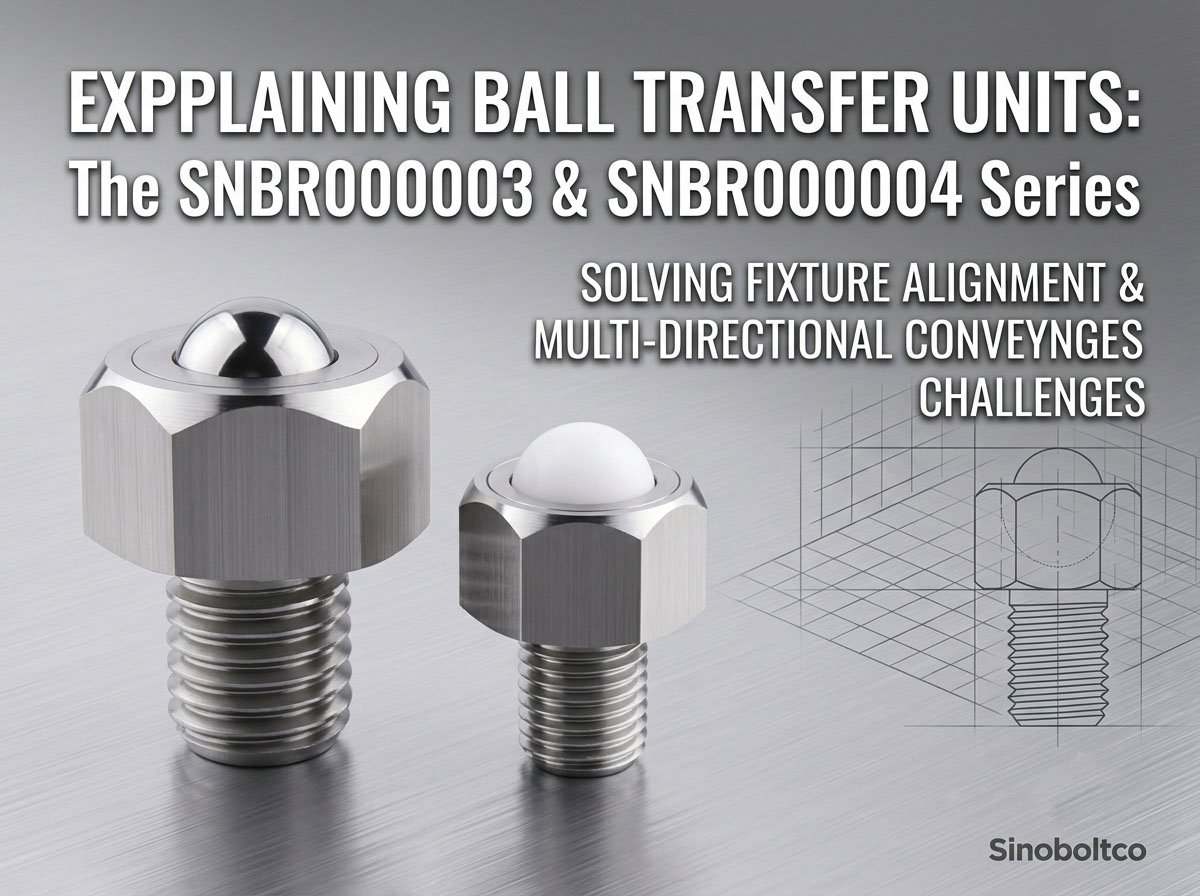
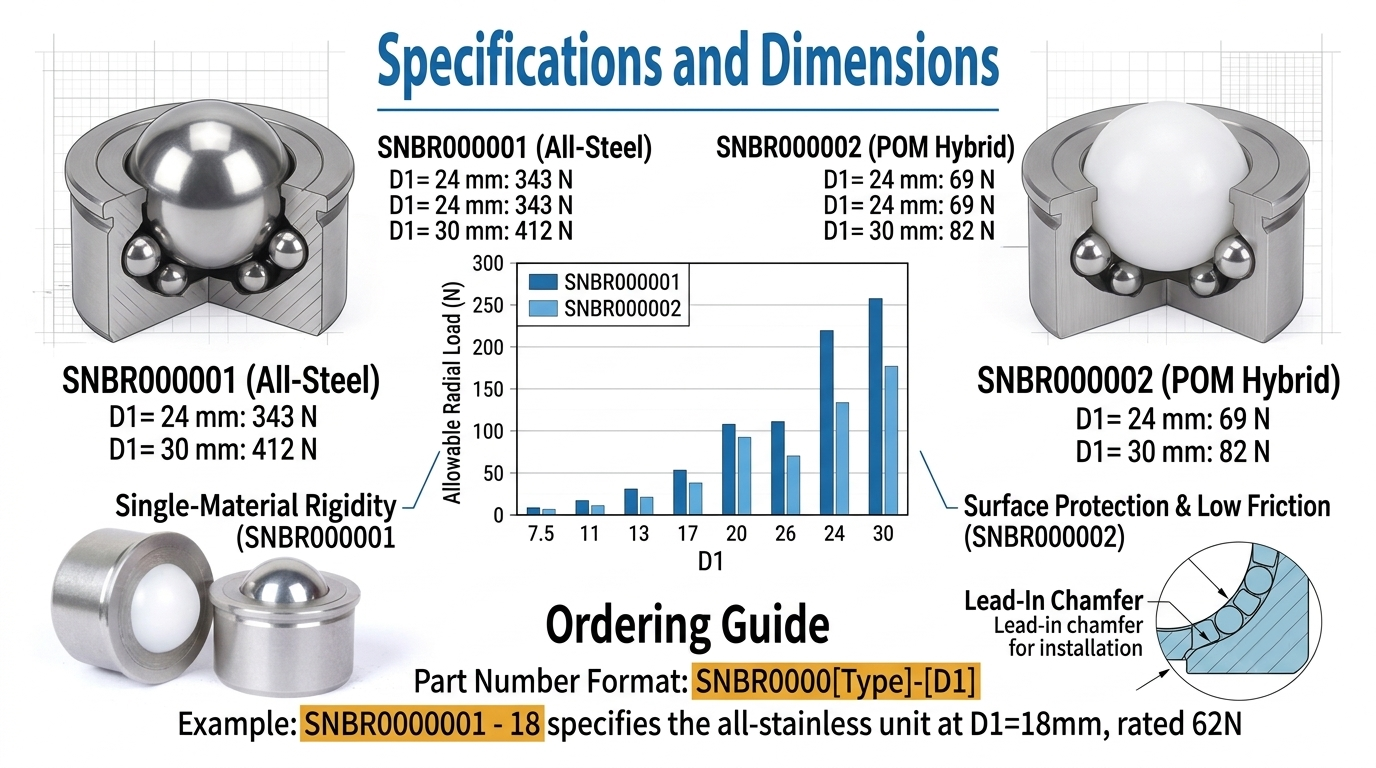
Small-scale automation has one recurring failure mode: designers spec a ball transfer unit sized for load, then discover the polymer main ball deforms under sustained point contact, or the metal-on-metal variant seizes once particulate contamination enters the raceway.
Material Configuration
SNBR000001 is a single-material system — body, spacer, sub-balls, and main ball are all stainless steel. There is no polymer interface, no elastomeric compliance, no thermal expansion mismatch between components. This is the correct specification when the load path requires consistent stiffness across the full temperature range, or when the application involves washdown, chemical exposure, or abrasive debris that would degrade a POM main ball over duty cycles.
For applications where noise reduction or lower friction against a softer mating surface is the priority, SNBR000002 — identical body geometry, POM main ball — is the correct substitution. Same D1/D/L/H envelope across the range, same mounting footprint, different load ceiling.
Load Data (Allowable Load, N)
| D1 (mm) | SNBR000001 | SNBR000002 |
|---|---|---|
| 7.5 | 12 | 6 |
| 9 | 14 | 7 |
| 11 | 41 | 27 |
| 15 | 55 | 34 |
| 18 | 62 | 55 |
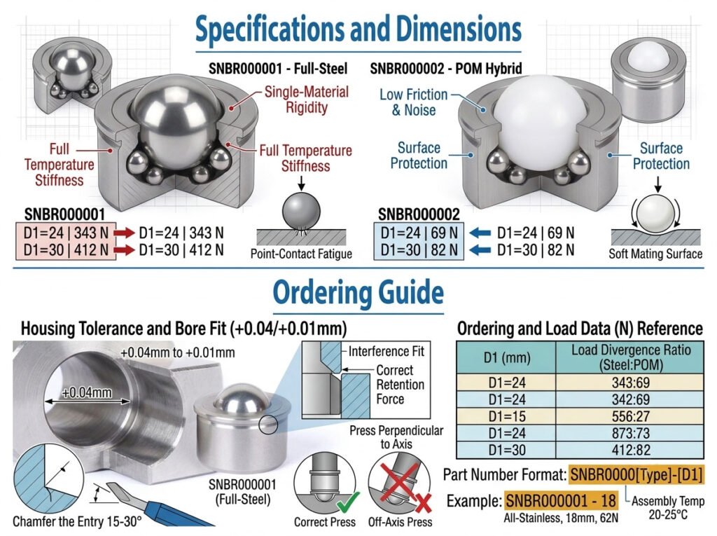
| 24 | 343 | 69 |
| 30 | 412 | 82 |
Note the divergence at D1=24mm and above: the all-steel main ball in SNBR000001 carries 4-5x the load of the POM variant at equivalent bore size. Below D1=18mm the gap narrows — for light-duty conveyance under 60N, either type will meet the spec, and the decision shifts to friction coefficient and acoustic requirements instead of load capacity.
Housing Tolerance
Bore tolerance is fixed at +0.04/+0.01mm across both types. This is a press-fit specification, not a slip fit — housing bore must be machined to this class to achieve the retention force the design assumes. A bore cut to a looser class will not seat the flange correctly and will compromise the load rating regardless of which type is selected.
Installation
- Chamfer the housing bore entry 15-30° to prevent galling on insertion — this applies to both types, since the body and spacer are stainless steel regardless of main ball material.
- Press perpendicular to the bore axis. Off-axis insertion on a full-steel unit risks raceway damage that a POM main ball would partially absorb; SNBR000001 has no such tolerance for misalignment.
- Hold assembly temperature at 20-25°C. Thermal contraction of the housing at low temperature reduces the interference fit and can allow the unit to work loose under vibration.
Ordering
Part number format: SNBR0000[Type]-[D1]. Example: SNBR000001-18 specifies the all-stainless unit at D1=18mm, rated 62N.