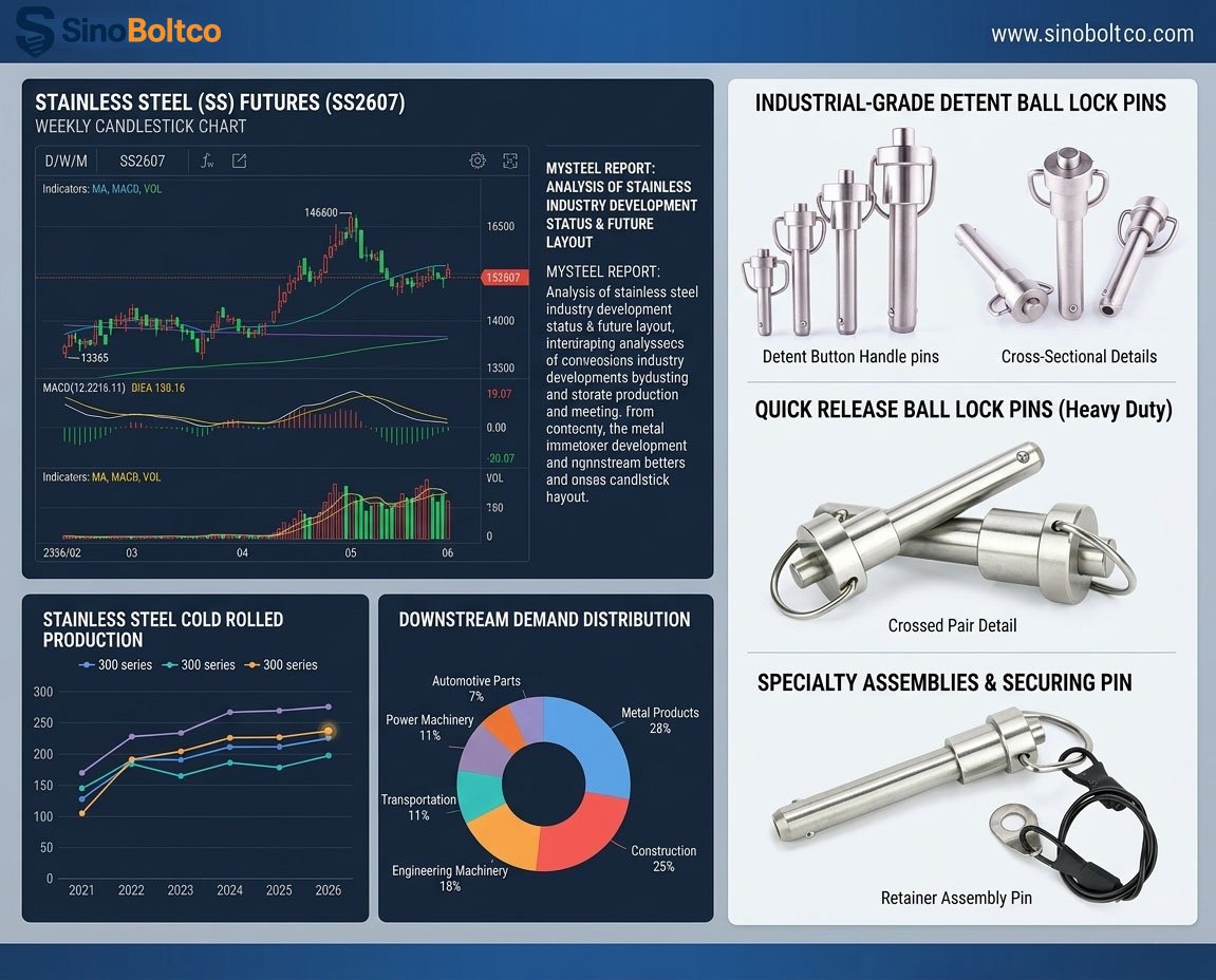
When your engineering project demands reliable, repetitive, and tool-free component fastening, standard bolts and cotter pins fall short. They slow down operations and are prone to loosening under vibration. This is where Heavy-Duty Ball Lock Pins (often referred to as quick-release or detent pins) become essential.
However, selecting the right quick-release pin requires more than picking a length out of a catalog. To ensure structural integrity and seamless integration, you must understand how to read a technical specification chart and match the pin’s dimensions to your application’s mechanical loads.
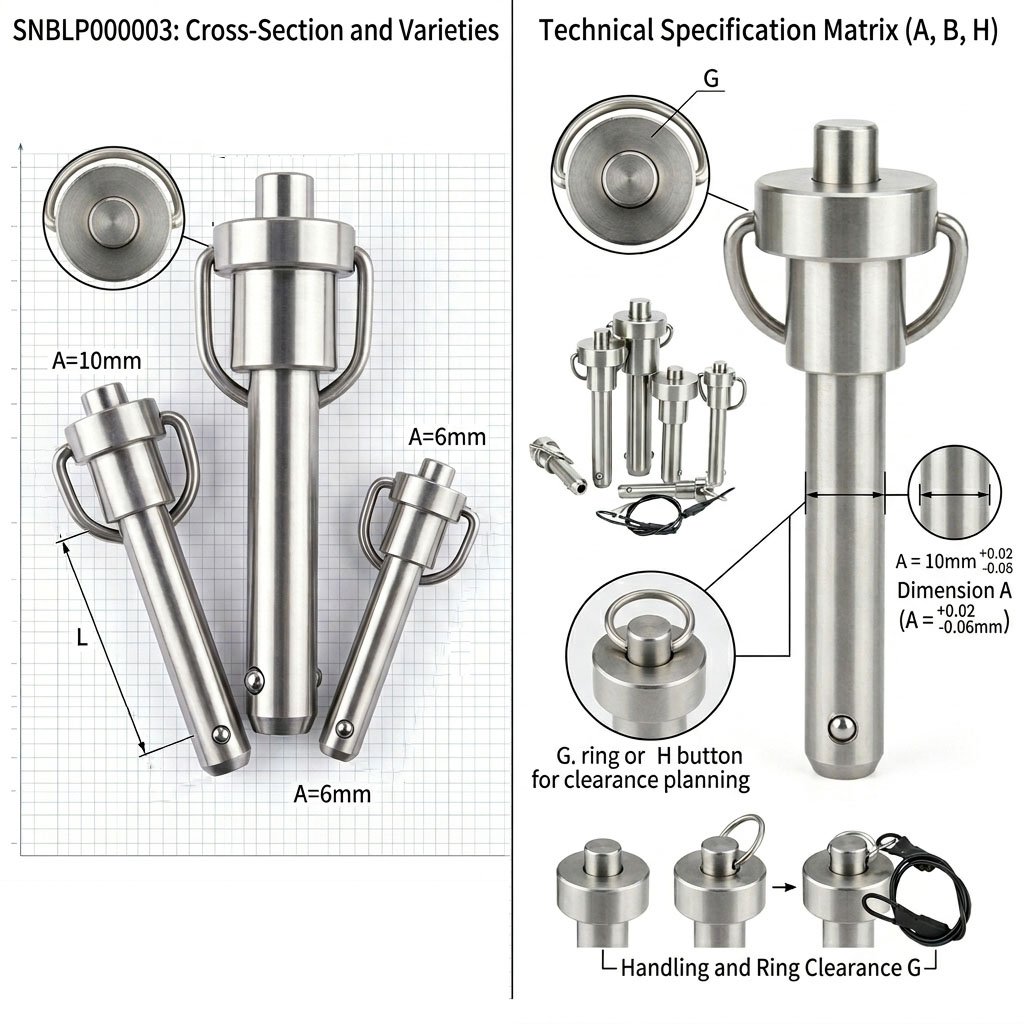
Below, we break down the critical engineering parameters based on professional specification standards using our standard specification system, Series SNBLP000003.
The receiving hole must be larger than A but strictly smaller than B to ensure the positive lock holds under load. If you are unsure which shaft diameter fits your standard receiving holes, you can check our complete [Stainless Steel Quick Release Pin Dimensions Chart] to find the exact mechanical match.
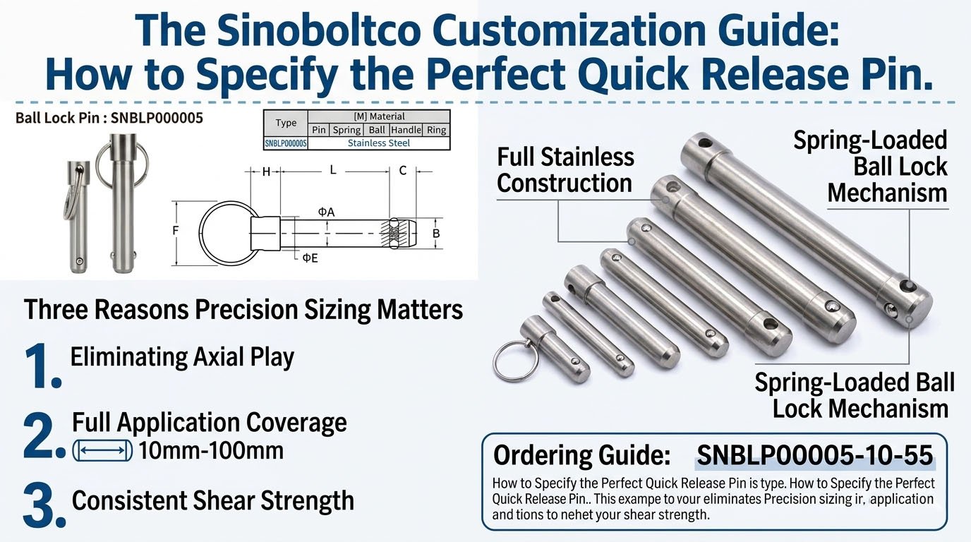
Decoding the Anatomy of a Ball Lock Pin
A quick-release ball lock pin operates via a positive locking mechanism. Inside the stainless steel shank, an internal spring-loaded plunger forces high-hardness locking balls outward. When the button at the head is depressed, the plunger moves, allowing the balls to retract so the pin can be inserted or removed.
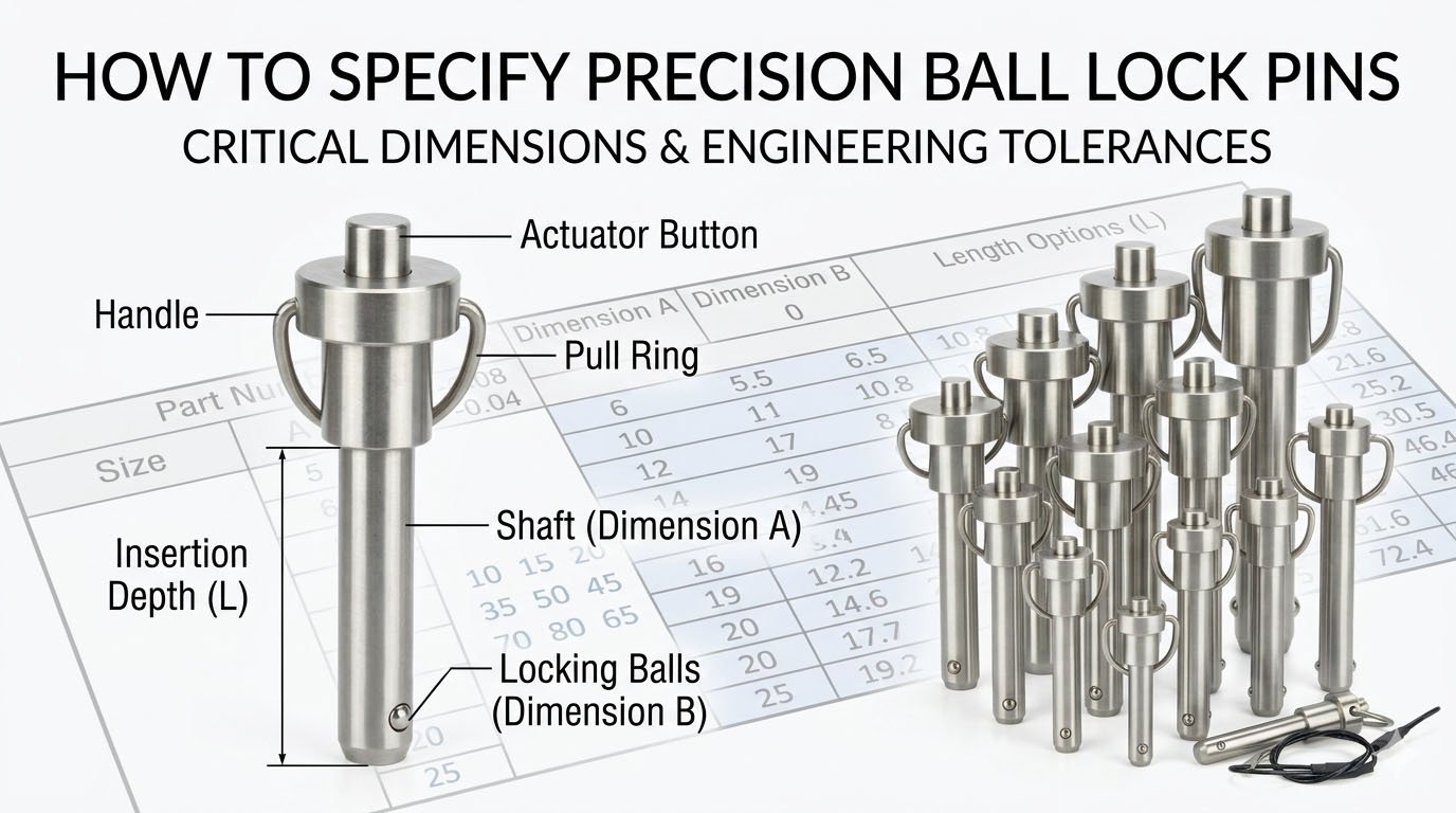
When engineering this into a system, you must design your receiver holes and clearance spaces around four primary variables found in the technical blueprint:
Shaft Diameter (Dimension A): This is the actual shaft diameter. Notice the tolerance on professional charts is typically negative (e.g., +0.00 / -0.08mm). This ensures the pin always slips smoothly into a standard-drilled hole without binding.
Insertion Grip Length (Dimension L): This represents the maximum depth the pin can insert into the mating object or fixture assembly. Your total workspace depth and fixture thickness must account for this L dimension to ensure a secure fit.
Total Ball Width (Dimension B): This refers to the total extended width, which combines the core shaft diameter plus the two projecting locking balls on either side. The receiving hole must be larger than A but strictly smaller than B to ensure the positive lock holds under load.
Pull Ring Clearance Length (Dimension G): This is the total length measured from the top shoulder of the cylinder down to the very edge of the pull ring. This dimension is crucial for calculating the required external clearance space for handling and rigging.
Button Actuator Length (Dimension H): This is the distance from the top shoulder of the cylinder to the tip of the release button. It tells you exactly how much clearance is needed to manually depress the button for release.
Engineering Dimension Reference Matrix
When specifying parts for your bill of materials (BOM), use the standardized engineering matrix below to match your load and clearance requirements (All dimensions in mm):
Size 5mm — Insertion Depth (L): 10 to 25 — Total Ball Width (B): 5.54 — Ring Clearance (G): 34.1 — Button Length (H): 20.8
Size 6mm — Insertion Depth (L): 10 to 45 — Total Ball Width (B): 6.99 — Ring Clearance (G): 34.1 — Button Length (H): 20.8
Size 8mm — Insertion Depth (L): 10 to 65 — Total Ball Width (B): 9.42 — Ring Clearance (G): 34.1 — Button Length (H): 21.6
Size 10mm — Insertion Depth (L): 10 to 85 — Total Ball Width (B): 11.86 — Ring Clearance (G): 38.0 — Button Length (H): 25.2
Size 12mm — Insertion Depth (L): 10 to 100 — Total Ball Width (B): 14.45 — Ring Clearance (G): 47.2 — Button Length (H): 30.5
Size 16mm — Insertion Depth (L): 10 to 100 — Total Ball Width (B): 19.00 — Ring Clearance (G): 61.6 — Button Length (H): 42.6
Size 20mm — Insertion Depth (L): 10 to 100 — Total Ball Width (B): 24.08 — Ring Clearance (G): 61.6 — Button Length (H): 46.4
Size 25mm — Insertion Depth (L): 10 to 100 — Total Ball Width (B): 30.97 — Ring Clearance (G): 72.4 — Button Length (H): 54.0
Key Takeaway for Clearance Planning: As the shaft diameter increases to handle higher shear forces, the external clearance geometry (G and H) expands significantly. For instance, upgrading from a 12mm pin to a 16mm pin increases the total pull ring clearance length (G) from 47.2mm to 61.6mm. Ensure your surrounding framework allows for this physical footprint.
Why Full Stainless Steel Construction Matters
In industrial manufacturing, medical equipment, and marine environments, material integrity is non-negotiable. Look for pins where all components utilize high-grade stainless steel:
The Pin and Ball: Must withstand high double-shear strength without deforming.
The Internal Spring: Cheap carbon steel springs will rust inside the shaft, causing the balls to seize in the retracted or extended position, leading to catastrophic failure or locked machinery.
The Handle and Ring: Ensures the operator can exert pulling force even in cold, wet, or oily conditions without fracturing the pull mechanism. For marine applications exposed to saltwater or chemical environments, we highly recommend browsing our premium collection of [Corrosion-Resistant Ball Lock Pins] to prevent internal spring failure.
How to Structure Your Part Number for Ordering
To avoid supply chain errors, configuration codes should always follow a strict Type – Diameter – Length structure.
Ordering Formula: [Part Number] – [Diameter (A)] – [Insertion Length (L)]
Example 1: If you need a 10mm diameter pin with a 55mm insertion length, your exact engineering spec is: SNBLP000003-10-55.
Example 2: For a heavy-duty 16mm diameter pin with a 80mm working insertion length, the spec is: [SNBLP000003-16-80]. You can enter this exact configuration code directly into our product page to complete your procurement.
Maintenance Best Practices for Positive Locking Pins
While these components are designed for thousands of cycles, harsh operating conditions require basic preventative maintenance:
Blow Out Debris: In woodworking, machining, or desert environments, fine dust can enter the button housing. Use compressed air regularly to clean the plunger track.
Axial Alignment Checks: Ensure the shear load is perpendicular to the pin. If the fixture shifts and applies torque or axial tension directly onto the locking balls, it can cause premature wear on the internal plunger.
Need Technical Drawings or CAD Files? If you are designing a custom fixture and require exact 3D step files or stress analysis data for the SNBLP000003 series, contact our engineering support team today.